")
In this article, we will build a solid understanding of computer networking by clearly naming each important concept, defining it precisely, explaining its real-world usage, and, where appropriate, walking through step-by-step processes so you can see exactly how these ideas are applied. You will learn what something is called, what it really means, why it exists in networks today, and how professionals or even beginners actually use or set it up. We will cover the material progressively, starting from the most basic building blocks and moving toward more advanced, but for this article, we will only cover the basics.

What Exactly Are Nodes and Transmission Media, and How Do They Work in Practice?
A node is any device connected to a network that is capable of sending, receiving, or forwarding data. This includes personal computers, laptops, smartphones, servers, printers, routers, switches, IoT sensors, security cameras, essentially anything with a network interface. The usage of nodes is to act as the active participants in all communication: end-user devices (like your phone) generate or consume data, while intermediary nodes (like routers) direct traffic between different parts of the network. Without nodes, there is no network at all. Transmission media are the physical or wireless paths that carry the signals between nodes. Wired media include twisted-pair copper cables (the most common for Ethernet in offices and homes), coaxial cables (still used in some cable internet setups), and fiber-optic cables (the gold standard for high-speed, long-distance backbone links because they transmit light instead of electricity and suffer almost no interference over great distances). Wireless media use radio waves (Wi-Fi), microwaves, infrared, or even satellite signals. The usage of transmission media is to provide the actual physical or electromagnetic pathway so data can travel; choosing the right medium directly affects speed, distance, reliability, cost, and security. For example, fiber is used for internet backbones because it can carry terabits of data over hundreds of kilometers with minimal loss, while Wi-Fi is used in homes and cafes because it allows mobility without running cables everywhere.
How the Internet Really Works – A Simple, Step-by-Step Explanation
What Each Size of Network Means and Where You Encounter Them Every Day
A Local Area Network (LAN) is defined as a network that covers a small geographic area, typically a single room, home, floor of a building, or small office. Devices in a LAN are usually connected via Ethernet cables or Wi-Fi and share the same broadcast domain, meaning they can communicate directly at very high speeds with almost no delay. The usage of LANs is to enable fast, low-cost resource sharing among a limited number of devices: printing documents from any computer to a shared printer, streaming movies from a home server to your TV, or transferring large files between colleagues in the same office.
A Metropolitan Area Network (MAN) is defined as a network that spans a city, large campus, or metropolitan region, connecting multiple LANs using higher-capacity links such as fiber rings or microwave towers. The usage of MANs is to provide city-wide or campus-wide connectivity: universities use MANs to link dorms, libraries, and lecture halls so students can access resources from anywhere on campus; some cities deploy MANs for public Wi-Fi hotspots or to connect government offices and traffic cameras.
A Wide Area Network (WAN) is defined as a network that covers large geographic areas, countries, continents, or the entire planet, often using leased lines, undersea cables, satellites, or public internet infrastructure. The usage of WANs is to enable long-distance communication: the global internet is the largest WAN, allowing you to video-call someone on another continent, access cloud storage hosted thousands of kilometers away, or connect branch offices of a multinational company so they can share the same database in real time.
Network Topologies Clear Definitions and Real-World Usages
Network topology is defined as the physical or logical layout of how nodes are interconnected in a network; it determines data flow paths, fault tolerance, ease of expansion, and overall performance. Its usage is to design networks that balance cost, reliability, speed, and manageability for specific environments.
 A star topology is defined as an arrangement where every node connects directly to a central device (usually a switch or hub), and all communication passes through that central point. The usage of star topology is widespread in homes and offices because it is simple to install, easy to troubleshoot (a cable problem affects only one device), and straightforward to expand, just plug in a new device. To set up a star topology step by step, first choose and install a central switch with enough ports for all your devices and ensure it is powered on and placed in a central location; next, run Ethernet cables (or configure Wi-Fi) from each computer, printer, or other node to one of the switch ports, making sure each cable is securely plugged in at both ends; then power on all devices and let the switch automatically learn their MAC addresses (this usually happens within seconds); finally, test connectivity by opening a command prompt or terminal on one computer and pinging another device’s IP address, if the ping succeeds, the star topology is working correctly, and you can begin sharing files or accessing the internet through a router connected to the same switch.
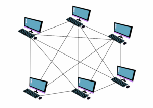 A mesh topology is defined as a configuration where many (or all) nodes are interconnected directly to several others, creating multiple possible paths between any two points. Its usage is in mission-critical environments, such as data centers, military networks, or wireless sensor networks, where redundancy is essential because if one link fails, data can reroute automatically through another path without interruption. Setting up even a partial mesh topology step by step starts with carefully planning which nodes need direct connections to achieve the desired level of redundancy without excessive cost; then equip each node with multiple network interfaces (wired ports or wireless radios); establish the chosen links by physically cabling them or configuring wireless point-to-point connections; configure routing protocols (such as OSPF or BGP in larger setups) on the nodes so they can dynamically discover all available paths and select the best one; finally, deliberately disconnect one link and verify that data still flows between the affected nodes via an alternative route, confirming the mesh’s fault tolerance.
How Hackers Really Think and Simple Ways to Stay Safe Online
The Layered Model: What Each Layer Does, Why It Exists, and How Data Flows
The layered model is defined as a structured way of organizing networking tasks into separate levels (layers), where each layer performs a specific function and only interacts with the layers immediately above and below it. Its usage is to make complex communication manageable, allow independent development of technologies at each level, and simplify troubleshooting (you can isolate problems to one layer). The seven-layer OSI model begins with the Physical layer, which is defined as the level responsible for transmitting raw bits over the transmission medium using electrical, optical, or radio signals. Its usage is to handle the hardware details of signal encoding and physical connectors, so higher layers do not need to worry about cables or wireless physics. The Data link layer is defined as the level that organizes bits into frames, adds local (MAC) addresses, detects and corrects errors on a single hop, and controls access to the shared medium. It is used to ensure reliable communication between directly connected devices, such as your computer and the nearest switch.
To see how data moves through the layers step by step, imagine you are sending an email attachment: at the application layer your email program creates the message and attachment; the presentation layer formats it (perhaps compressing the file or converting character encoding); the session layer establishes and maintains the logical connection between your email client and the recipient’s server; the transport layer breaks the entire message into numbered segments and adds reliability checks (using TCP) or just sends them quickly (using UDP); the network layer adds global IP addresses and determines the route across multiple networks; the data link layer wraps each packet into a frame with the MAC address of the next hop and error-checking codes; the physical layer converts the framed data into signals and sends it over the cable or airwaves; at each intermediate router the process reverses up to the network layer to make the next forwarding decision, then goes back down the layers to the next link, repeating until the data reaches the destination where the layers reverse the process to reconstruct and deliver the original email.
Why This Structured Approach Matters for Learning and Using Networking Today
By clearly defining each concept, showing exactly where and why it is used in the real world, and walking through step-by-step processes in plain language, this article aims to give you just the basics and a usable understanding. You now know what a node is and why it matters, what a star topology looks like and how to set one up yourself, and exactly how your data travels through layers when you send a message. These foundations allow you to troubleshoot Wi-Fi problems at home, understand why your office network is designed the way it is, and follow more advanced topics like cloud networking or cybersecurity with confidence. Keep returning to these definitions and processes; they are the building blocks on which everything else rests. Next, we will dive deeper into the other types of topologies and their usages.